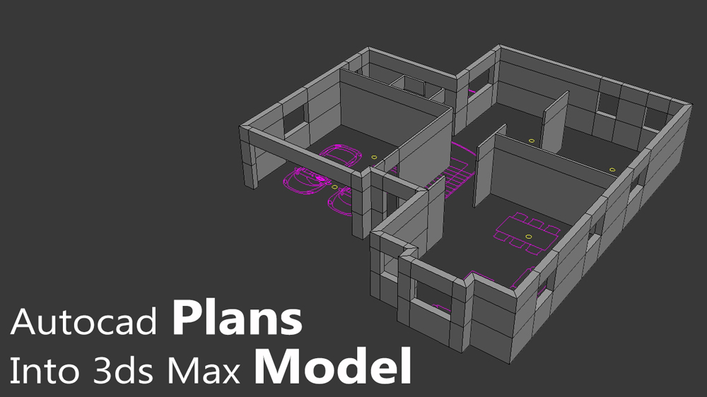
Almost all of my 3d rendering projects start with an architectural drawing, usually done with AutoCAD by an architect or interior designer.
When a client send me his building plans, 99.9% of the time they will contain a lot of information that I might not need, or that would make it very difficult for me to “read” the building outline in order to import it to a 3D application.
Such information could be; electrical wiring, dimensions, text, symbols, hatches, topography measures and so on.
Your goal is to prepare the plans as much as you can in 2D before you even opened your 3D application.
So how does one go about doing that?
Here are the main steps which I’ll go over in this tutorial:
- Hide/delete all non-relevant objects.
- Create new layers for each element.
- Trace building lines.
- Clean up and flatten your plan.
- Import to 3d application.
- Convert lines to 3d model.
Hide/delete all non-relevant objects
This is the first step you should do in order to have a better look at your project. The most basic elements that should be visible are the walls, stairs, sections and elevations.
Beside those I like to keep other 2D elements that will help me later on when placing 3d objects, such as furniture, light fixture’s positions, sanitary, kitchen elements and the exterior area.
I will only be using those as a reference guide after importing into 3ds Max.
If the AutoCAD file was well organized by layers (as it should be), then your life would be much easier, because you could just turn off all the unnecessary information and keep only the ones you need.
Select the “turn layer off” icon ![]() and start picking the lines you like to hide. If a line you’ve just selected is still visible, that because it’s part of a block reference or the line’s layer is currently selected. Just explode the block and/or move to a different layer.
and start picking the lines you like to hide. If a line you’ve just selected is still visible, that because it’s part of a block reference or the line’s layer is currently selected. Just explode the block and/or move to a different layer.
This is the before and after:

In case the drawing isn’t organized by layers, you’ll have to work a little bit harder and delete/hide the unnecessary lines by hand.
Create new layers for each element
Now that we have left only with the information that we need, it’s time to create new set of layers for each element.
Why separate by layer?
because every layer that is imported to 3ds max is converted to one spline object which will become one 3d object later on.
I usually create the following layers for each element:
- 3d_walls_out
- 3d_walls_in
- 3d_lights
- 3d_furniture
- 3d_floors
These are the basics ones, but you can create as many as you like.

Trace the building lines
This is the part where you might work a little to trace all of the building lines, especially if it’s a big building with different floor layouts. But trust me, it will make your life much easier when moving into 3ds max later on.
There are two main methods that I use to trace the inner and outer walls, sometimes I’ll use them both and sometimes just one of them, for the sake of this tutorial I’ll show you one on the inner walls and one on the exterior walls.
Start by selecting layer “3d_walls_out” and with the polyline tool trace only the outer line of the exterior walls. Click on one corner of the building and continue by clicking on every window or door opening and on every wall corner.

After you’ve circled around the building, click “C” to close the spline just before your initial starting point. The walls thickness will be added later on with the help of the shell modifier.
The second method will be to trace all around the wall itself. Select the layer “3d_walls_in” And start clicking on the inner walls with the polyline tool.
This time, stay only on the wall itself without “jumping” over gaps of doors and windows, click “C” right before you get to the starting point again. Do the same for every inner wall.

After tracing all the walls, I’ll continue by moving all other elements to the new layers that I have created earlier; furniture, lights, kitchen and so on. Again, I will use those just as a reference.
Clean and flatten your plan
Most of the 2D plans that I get, tend to have several issues that will give me hard time when importing to 3ds max, if not fixed first.
The most problematic ones are lines that are too far from grid’s origin (0,0), which will make you viewport flicker and other unexpected bugs in side 3ds max.
The other main issue is when you have lines with Z position other than 0.the plan should be flattened completely on the Z axis.
I’ll start by selecting all the lines and copy them (Ctrl+C on keyboard) to a new AutoCAD document. Paste (Ctrl+V) and click near the grid’s origin and save to a new file.
Next, switch from top to front view to check if there are any lines not zeroed on Z axis. If so, select them and write “flatten” in the command line.
Another option is to select the lines, then right click to select their properties. Go over each of the line type and insert 0 in the Z position or elevation section.

After doing that, I like to use 2 more commands to get rid of excess information. The first one is the “overkill” command for overlapping lines and the second is “purge” command for deleting empty layers and stuff like that.
Import into 3ds Max
Importing to 3ds max is quite easy, in the file menu click on import and select the new AutoCAD file. A window will open up with import option. I leave most of the options as default.
Make sure to set the incoming file units the same as the DWG file, in my case the file units are in millimeters so I’ll set the units to millimeters as well.
Make sure that “layer, blocks as node Hierarchy is selected” and that “weld nearby vertices” is off.
Next, go to the layer tab, click on none to deselect all the layers. Then select by hand only the layers that you’ve created earlier in AutoCAD. Click ok to continue.

Convert lines to 3d model
Basically, the import stage is done. I will show you however, how easy it is now to convert these lines into 3d model.
Select the inner walls and add extrude modifier to it. Set the height of the wall and convert it to editable poly.

Next, we need to slice the walls horizontally, at the top of the doors opening. Under vertex mode (press 1 on keyboard), select slice plane and set its height to 210 cm, click on “slice”.

Deselect the slice plane and move to polygon mode (4 on keyboard). Select the polygons above each door and bridge them together.

For the exterior walls we need to do pretty much the same, select the spline, add extrude modifier and enter walls height.
Convert to editable poly and slice with the slice plane as before, only this time, you need to slice at the bottom of the windows opening as well. Select all windows and doors polygons and delete them.
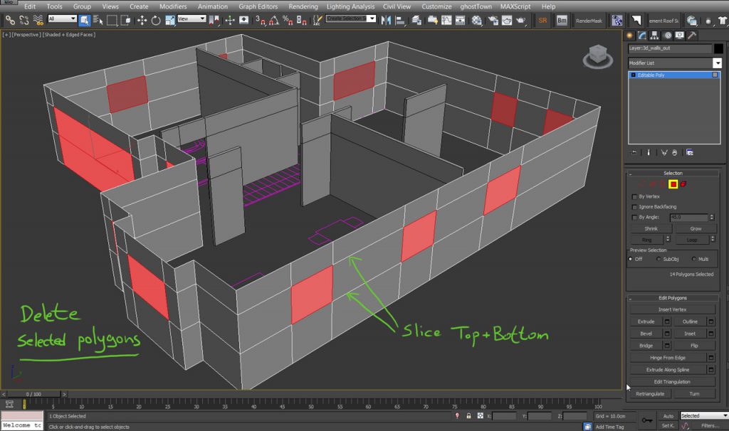
Add shell modifier and set wall thickness. If the corners of the walls seem to be distorted, then click on “straighten corners” at the bottom of the shell modifier.

It might look like a hassle when doing all these preparation in 2D first, but it actually saves allot of time later on, especially while working on a big project.
If you have different approach of importing 2d plans in to 3d application I’ll be happy to hear about it in the comments below!
Cheers.
Simple yet great tips, It’s the same approach I’m using for years, but still I learnt some little details.. Thank you so much 🙂
Thanks Omar!
i like this tutorial, but i not understand on the “clean and flatten the plan” step..
please explain for this step or add the short video, gif to make me understand
thanks..
sorry for my english
Hi Rifan
I’ll try to better explain this section:
1.Make sure that the plan is near the XYZ grid origin.
2.delete overlapping lines by selecting all and writing OVERKILL in the command line, delete unused elements such as empty layers by selecting all lines and writing PURGE in command-line and PURGE ALL.
3.Make sure that the plan is completely flat. Moving from top view to side view you should see a single horizontal line. If you see more than one line then it means that you have some lines along the Z axis. Select them and set the Z value to 0 by right clicking->properties, or by using the FLATTEN command.
Hope I made it more clear 🙂
Thanks for your article. I tried extruding the spline which worked perfectly. I selected the vertex after converting with edit poly modifier, adding the slice modifier, I tried bridging the polygons above the doors, it didn’t highlight, please what could be the problem??
Nice one,but after using “shell” walls inside arent straight (polygons near corners),any idea how to fix it?
Under the shell modifier scroll down and select “Straighten Corners”.